Box
Interface A
Power
Cable
IBM card
| Back |
| Home |
The LEGO Technic Interface A system consists of the Interface itself along with a power supply, a cable and either an IBM or Apple interface card. Also required were IBM (DOS) or Apple software diskettes including LEGO TC Logo or Logo Lines. I am very much interested in the IBM (DOS) software, if anyone has it for download or even the original diskettes.
|
|
|
|
|
Box |
Interface A |
Power |
Cable |
IBM card |
|
|
|
|
|
Interface A other views |
||||
|
|
|
|
Packaging |
IBM card |
IBM card |
US Power |
The Interface A is designed for use with some specific pieces:
|
|
|
Optosensor |
Disks |
Touch Sensor |
|
|
|
Motor |
Wire |
Lights |
In order to use the Interface A with semi-current computers, I discovered that others, namely Burf2000 from Eurobricks had successfully used the Parallel Port from a PC with a custom cable and Visual Basic. Therefore, now knowing it was possible, I discovered the pin-outs for the Interface A from here and wired them to a Parallel Port DB25 connector. I used the first six Data Port pins for outputs, the fourth and fifth Status Port pins for inputs, and the first two Control Port pins to supply +5V.
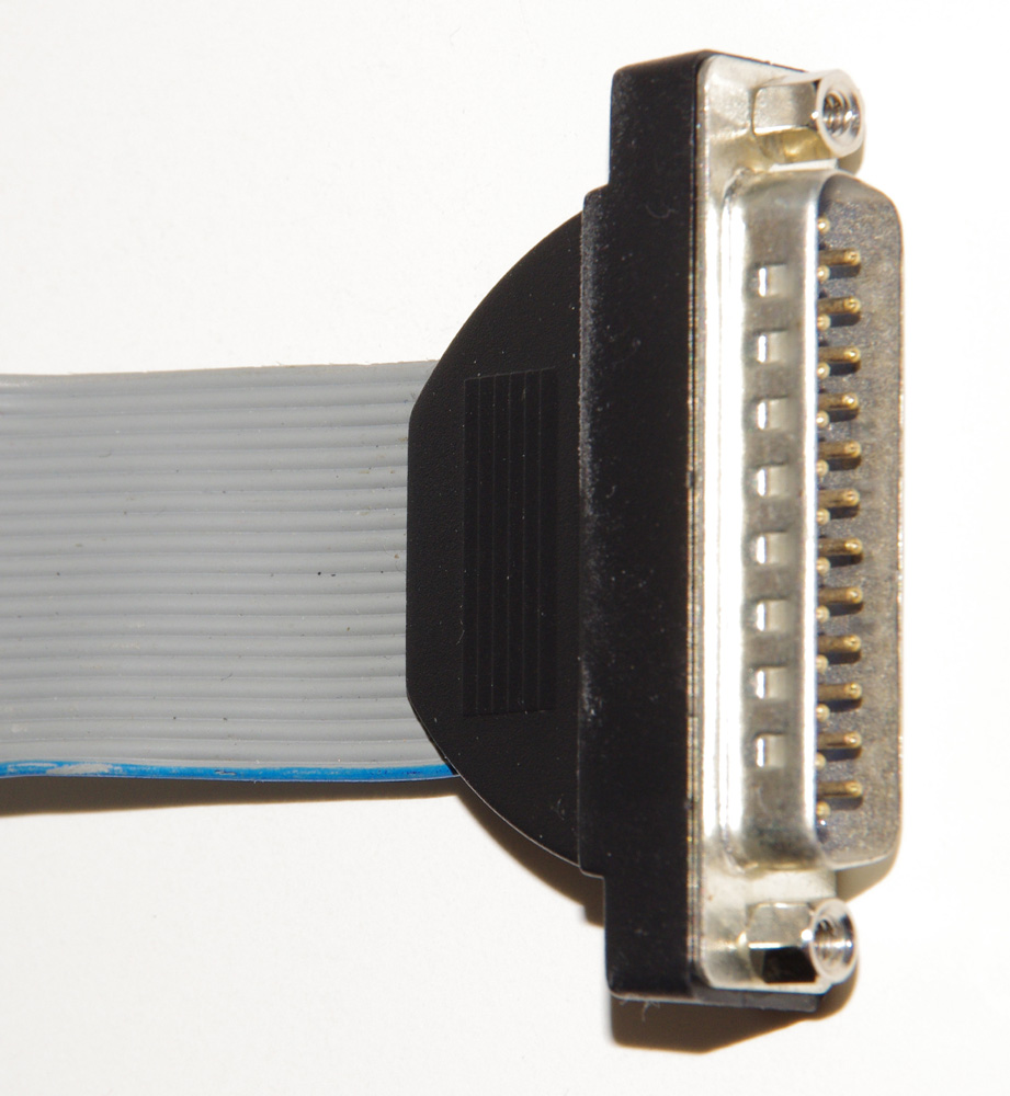
To build the custom cable I used a standard 20 conductor ribbon cable with a 20-pin IDC connector on one end. The other end will need to be cut, stripped, and soldered to a male DB25 connector. I found a ribbon cable in my junk box. You can purchase one or you could use the LEGO cable by cutting off one of the connectors. For the DB25 connector, I used an old 25-pin serial PC back plane.
|
|
|
|
|
20-Pin |
DB25 Male |
DB25 Top |
DB25 Bottom |
Completed Custom Cable |
Each wire from the Interface A 20-Pin connector was attached to the male DB25 connector as follows:
LEGO Cable Pin |
LEGO Cable Function |
Parallel Port DB25 Pin |
Parallel Port Function |
1 |
VCC: +5V |
1 |
Control 0 |
2 |
- |
- |
- |
3 |
VCC: +5V |
14 |
Control 1 |
4 |
- |
- |
- |
5 |
Ground |
18 |
Ground |
6 |
Output Bit 0 |
2 |
Data 0 |
7 |
Ground |
19 |
Ground |
8 |
Output Bit 1 |
3 |
Data 1 |
9 |
Ground |
20 |
Ground |
10 |
Output Bit 2 |
4 |
Data 2 |
11 |
Ground |
21 |
Ground |
12 |
Output Bit 3 |
5 |
Data 3 |
13 |
Ground |
22 |
Ground |
14 |
Output Bit 4 |
6 |
Data 4 |
15 |
Ground |
23 |
Ground |
16 |
Output Bit 5 |
7 |
Data 5 |
17 |
Ground |
24 |
Ground |
18 |
Input Bit 6 |
12 |
Status 5 |
19 |
Ground |
25 |
Ground |
20 |
Input Bit 7 |
13 |
Status 4 |
With the cable constructed, I could now program the Parallel Port to write and read, to and from, the Interface A. I used Visual C# 2010 Express, and InpOut32 DLLs to write a small windows application. I started with the fundamentals of Parallel Port communications from here and here.

The key communication bits are:
1. Only use the first six Data Port outputs (D0 – D5); D6 and D7 are not used and are not connected.
2. Only use S4 and S5 of the Status Port input for Inputs 6 and 7 of Interface A; S3, S6, and S7 are not connected and are ignored.
3. Always turn on C0 and C1 of the Control Port to supply +5V; C2 and C3 are not used and are not connected.
Also, the software must be given the Address of the Parallel Port (Default of 378 Hex), which corresponds to the Data Port. To read the Status Port, the program uses Address+1, and to write to the Control Port, the program used Address+2.
The program can be downloaded here LEGOInterfaceAexe.zip; this includes the executable plus the two DLLs (32 and 64 bit versions). Simply place all three files in the same folder and run the executable.
The source code can be downloaded here LEGOInterfaceAsource.zip; this includes the Visual C# project files. Expand the zip file and place in the Projects folder for Visual C# Express.
Visual C# Express: http://www.microsoft.com/visualstudio/en-us/products/2010-editions/visual-csharp-express
DLLs for Parallel Port access: http://www.highrez.co.uk/Downloads/InpOut32/default.htm
Visual C# sample code: http://thaiio.com/prog-cgi/CshapeParallelPort.htm
Reading from the Parallel Port: http://www.codeproject.com/KB/vb/Inpout32_read.aspx
Parallel Port information: http://www.beyondlogic.org/spp/parallel.htm
LEGO Technic Set No. 1093 (LEGO Interface A) Instructions: http://isodomos.com/Lego-Sets/1093.html
LEGO Technic Set No. 9700 (LEGO Computer Interface Unit Manual): http://isodomos.com/Lego-Sets/9700.html
LEGO Technic Set No. 9767 (Interface Card and Cable for TC Logo - Apple IIe and Apple IIGS) Instructions: http://www.1000bit.it/support/manuali/apple/lego9767/lego9767p.pdf
LEGO Technic Robotica: http://www.miniland.nl/Dacta/robotica.htm
I hope you have as much fun and “Play Well” with your LEGO Interface A as I have. If you have any questions, please let me know at tom@lgauge.com.