
DRAFT 10 March 2000
Here’s an attempt to describe how I implemented DCC into LEGO Trains:
Table of Contents:
What is DCC?
Disadvantages and Advantages of DCC with LEGO Trains
Equipment required for DCC
Command Station
Decoders
Decoder Installation
Parts Lists
Operation
Conclusion
Digital Command Control (DCC) is a system where signals are transmitted through the track to decoders installed locomotives (or any device connected to the track). The decoders translate these signals into speed, direction, and on/off commands (e.g., headlights). DCC can also be used to control accessories, such sound effects and switch-machines.
Disadvantages and Advantages of DCC with LEGO Trains
Disadvantages:
Advantages:
DCC systems employ a few components such as:
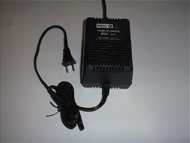
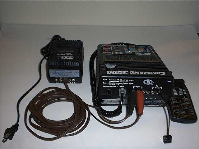
For a command station, I purchased the MRC (
www.modelrec.com) Command 2000. This command station will handle about 2.5 amps (all trains). It requires an AC power supply of slightly more than that. MRC also sells an appropriate power supply, so I purchased both of these at my local Hobby Shop. Later, also at my local hobby shop I purchased the MRC Handheld (tethered) Controller for the Command 2000. All of this equipment is also available through mail-order and internet dealers.
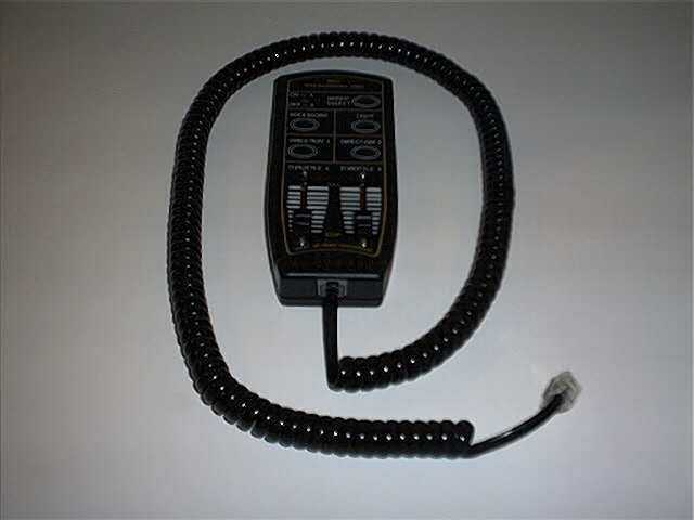
This system allows me to run two groups of five trains simultaneously. Three throttles are built into the Command 2000, and the Handheld controller includes two throttles. However, to run ten trains I must switch back and forth between the two groups, and use the SAME five throttles to run another five trains.
There are other DCC systems which allow many more trains and more sophisticated controllers (e.g., radio control), but the controllers are sold separately. The added capabilities and extra throttles doubled my estimated cost, so I chose the MRC option (for now).
As for the decoders, I chose the Digitrax (
www.digitrax.com) DN140, N-scale decoder. I chose this decoder because it fits nicely into the LEGO train motor without any modifications, and supports functions such as Maximum Voltage and the Loadable Speed Table which allows you to set 28 throttle increments to a percentage of full throttle. This allows you to define a "speed curve", and it allows you to limit the voltage to the motor. HO and N scale DCC systems deliver about 12VDC to the motor at full throttle (G guage even more). I wanted to limit the LEGO train motor to about 9VDC, so I defined a curve with 0% at zero throttle and 75% and maximum throttle, and used a parabolic function to fill-in the remaining steps. This gives me finer control at the slow speeds and coarser control at the high speeds. (I’m still playing with this speed curve for optimum response).
First I had to overcome the horror of cutting the tabs off the train motor. After that, I used an X-acto knife, wire strippers, a soldering iron, solder, and the steps below to install the decoders:


Since the MRC Command 2000 will not program special functions, I purchased
the Digitrax PR-1 computer programmer. This device plugs into a standard RS-232
serial port and comes with software to program decoders. The PR-1 also requires
a DC power supply to operate, so I purchased a simple wall transformer from
Radio Shack. I also soldered a jack to the PR-1 input wires, so I could plug the
wall transformer output into the PR-1. Additionally, I soldered alligator clips
to the two other wires of the PR-1 so I could connect it to any track easily.

Using the PR-1 software, I entered the following 28 speed step values to
obtain a parabolic function and wrote them to the decoder:

Next, I set the options as follows and wrote them to the decoder:

If you are willing to let the motors run up to 12V and do not care about the speed curve function, you do not need to program the decoders in this manner. You can just use the MRC 2000 as is. Leaving the decoder at the default 12V maximum may give the desired boost when the voltage drops when under heavy load. However, you will need to be careful when running these motors without a load, because they will travel incredibly fast.
Programming is now complete
.The following chart lists all the equipment I used to implement DCC:
| Quantity | Item | Manufacturer | Possible Source | Source Part No. | Unit Price |
| 1 | Command 2000 AD090 | MRC | Standard Hobby Supply | M14-AD090 | $108.99 |
| 1 | Twin Power Box AH800 | MRC | Standard Hobby Supply | M14-AH800 | $31.99 |
| 1 or 2 (optional) | Walk-Around 2000 AD300 | MRC | Standard Hobby Supply | M14-AD300 | $29.99 |
| 1 | LEGO cable | LEGO | Shop at Home (800-453-4652) | 5111 | $4.50 |
| 1 | LEGO track connector | LEGO | Shop at Home (800-453-4652) | 5303 | $6.75 |
| 1 for each motor | Decoder DN140 | Digitrax | Springhaven Shops | DN140 | $40.00 |
| 1 (optional for speed table) | Computer Programmer PR-1 | Digitrax | Springhaven Shops | PR-1 | $40.00 |
| 1 (optional with PR-1) | Wall Transformer | Any | Radio Shack | 273-1662 | $12.99 |
| 1 (optional with PR-1) | Jack | Any | Radio Shack | 910-0908 | $1.99 |
| 2 (optional with PR-1) | Alligator Clip | Any | Radio Shack | 27-378 (set of 10) | $2.79 |
| 1 | Lamp Cord | Any | Radio Shack | ??? | |
| 2 | Spring Clip | Any | Radio Shack | 27-349 (set of 4) | $2.49 |
| 1 for each motor with headlight | Resistor, 1/4 W, 78.7 W | Any | Digi-Key | 78.7XBK | 5 for $0.54 |
| 1 for each motor (optional) | Resistor, 1/2 W, 2.2 W | Any | Digi-Key | 2.2H | 5 for $0.27 |
| 5 for each motor (optional) | Capacitor, 22 mF, 25 V, bi-polar | Any | Digi-Key | P1177 | 10 for $2.71 |
To setup the MRC DCC system, I first cut the LEGO
connector off one end of a LEGO cable, and then stripped the insulation from the
wires and connected them to the "Track" terminals on the MRC Command
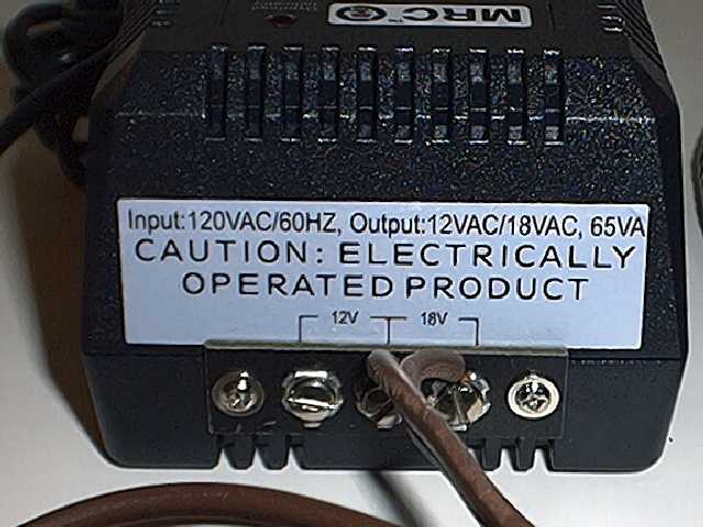
2000. Next, I used a piece of lamp cord (2 conductor) to connect the power
supply to the MRC Command 2000. I stripped the wires on one end of the
lamp cord and connected them to the 18V output of the Power Supply. For
the other end of the lamp cord, I attached spring clips so I could easily
disconnect the the Power Supply from the MRC Command 2000. Now all that is
necessary is to connect the spring clips to the MRC Command 2000 input, plug-in
the Power Supply, and attach the LEGO connector to a standard LEGO track
connector wire.

To operate the DCC equipped LEGO train motors, I hook up the Command 2000 to the track, set it to Program mode, and place one motor on the track and program the desire channel. Only program one motor at a time. If more than one motor is on the track when you set the channel, all of those motors will be reprogrammed too. I use a separate piece of isolated track to program the motors so I do not have to take all the other motors off the track. Setting the channel with the Command 2000, I must remember to ONLY change the channel. Otherwise I will reprogram all settings to the default values and the motor will no longer use the speed curve. Programming of decoders is only required once. Each decoder will remember its last settings until reprogrammed.
Once I have all the motors programmed, I change the Command 2000 to Run mode and begin operating the trains.
This system in not yet perfected. I am currently investigating using the Digitrax command station with radio control throttles. This will allow wireless operation, virtually unlimited locos, and true MU capability, but the cost will be significantly higher. Soon (I hope) I will attempt to use one of the Digitrax decoders which reads back EMF and can boost the output when the loco is drawing a load. Hopefully, this will help the locos maintain a more constant speed. I am also investigating additional ways to reduce the buzzing noise at slow speeds. I have discovered that certain models amplify the noise, such as hollow diesels. Solidly built locos, on the other hand, seem to run more quietly.
I hope this information was useful to you. Please feel free to contact me with any questions, comments or constructive criticisms at
cook_thomas@csi.com.